Skip to content

Paynesville City · Monrovia · Liberia

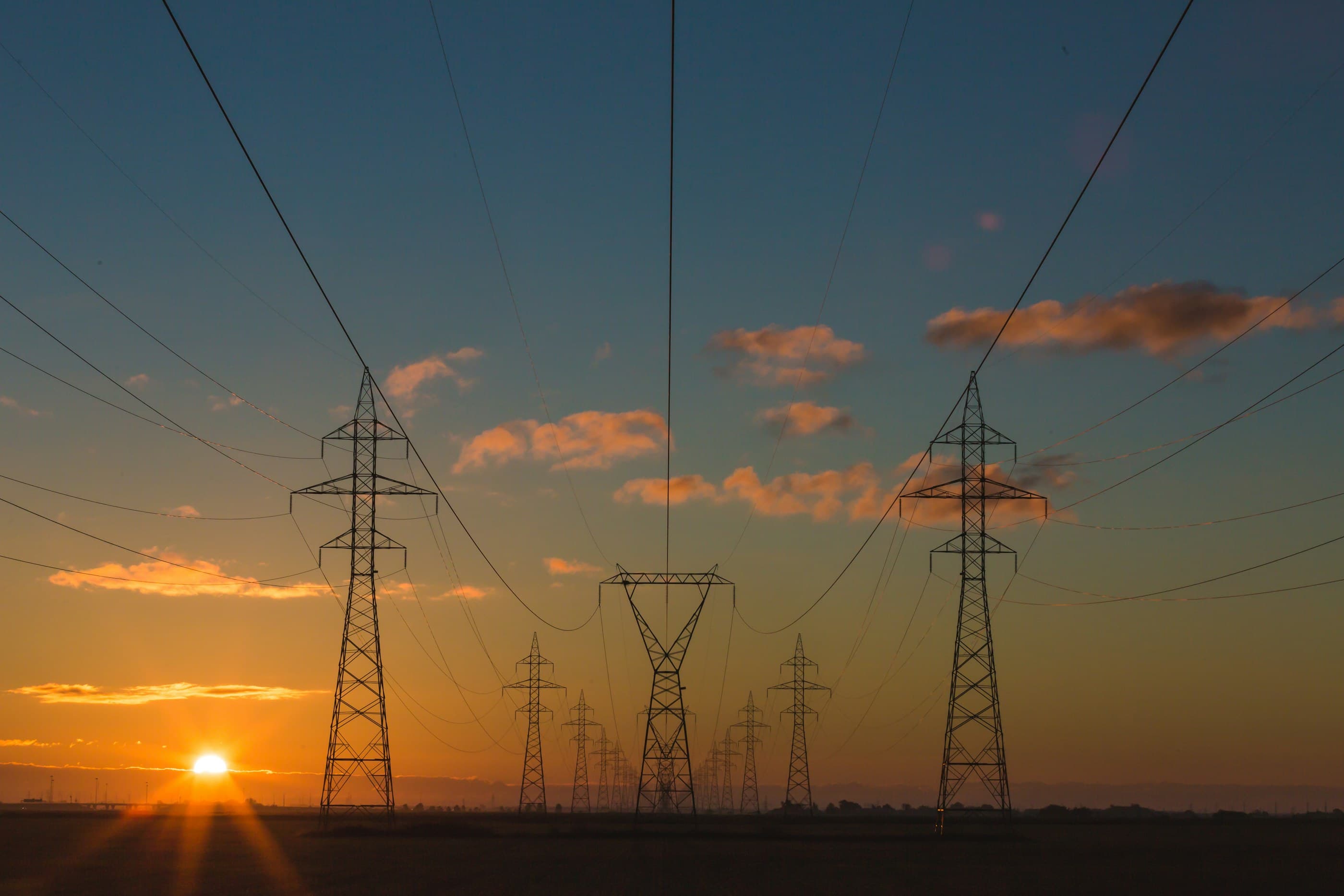
A high-voltage transmission corridor at dusk, silhouetted against a sky running from deep blue through magenta to a narrow band of amber at the horizon.

Licensed stock · illustrative

Thermographic monitoring · Structured cabling · Power

Every hotspot.
Before it burns.

A loose connection runs hot for months before it fails. We install the cameras that watch for it continuously — and the cabling, power and backhaul that keep them watching.

Thermal / visual comparator

Synthesized · not a client site

VisualInfrared
25°38°50°63°75°
Ironbow palette · apparent temperature
Three-phase cable termination onto a busbar. Drag to compare the drawing against the infrared frame. Readings are published in full below and do not depend on the slider.
Radiometric spot readings for Three-phase cable termination onto a busbar
SpotComponentReading
Sp1R-phase terminationreference46.2 °C
Sp2Y-phase termination45.1 °C
Sp3B-phase terminationanomaly68.6 °C

ΔT vs Sp1

22.4°C

Major discrepancy

Repair immediately. Measured against a similar component under similar loading.

ΔT against band

axis truncated at 32 °C

02Failure mode

Heat is the early warning. It is also the damage.

Nothing in a switchroom fails without warming up first. The warning is free, it runs for months, and almost nobody is looking at it.

  1. 01

    The joint loosens

    A bolted connection relaxes, or corrodes, or was never torqued properly. Contact area falls. Resistance across the joint climbs.

  2. 02

    Current turns into heat

    Power wasted in the joint rises with the square of the current — double the load and the heating quadruples. A joint a few milliohms out of spec becomes a heat source.

  3. 03

    The damage compounds

    Sustained heat degrades insulation and anneals the conductor. The joint gets worse at shedding heat, so it runs hotter, so it degrades faster.

  4. 04

    It fails unplanned

    The joint arcs, protection trips, and the outage happens at the worst possible time. The window in which this was a ten-minute repair closed months earlier.

Insulation ageing roughly doubles for every 6 °C of sustained temperature rise at the reference band.

IEEE C57.91 loss-of-life ageing factors: F_AA 1.0000 at 110 °C, 0.5362 at 104 °C, 0.2817 at 98 °C.read at source

A radiometric camera reads surface temperature, not winding hot spot. It flags the condition; it does not replace an oil test.

Around 63% of major transformer failures originate in components that carry a thermal signature — windings 37.7%, bushings 15.9%, on-load tap changers 9.4%.

CIGRE Technical Brochure 642: 964 failures over 167,459 transformer-years, 56 utilities, 21 countries.reported, not verified at source

The same study finds no age-based failure curve. Age alone does not justify replacement — which is precisely the argument for monitoring condition instead.

03The evidence

Four numbers worth arguing from.

Each of these carries its source and its limits. A large figure with nothing behind it is the most template-looking thing a contractor can print — and on a tender page it is an unsupported claim set in very big type.

of major transformer failures

63%

of major transformer failures

begin in windings, bushings or tap changers — components that warm measurably before they let go.

CIGRE Technical Brochure 642: 964 failures over 167,459 transformer-years, 56 utilities, 21 countries.The same study finds no age-based failure curve. Age alone does not justify replacement — which is precisely the argument for monitoring condition instead.

opens the first action band

1–3°C

opens the first action band

A differential that small against a comparable component already warrants investigation. Cameras sold for perimeter detection are specified at ±5 °C and cannot resolve it.

ANSI/NETA MTS-2023, Table 100.18, Section 9.The table classifies by the basis a reading was taken on. Against ambient the same first band opens at 1 °C to 10 °C — quoting one threshold without naming its basis is meaningless.

typical payback on IR thermography

≤ 12months

typical payback on IR thermography

Across independently surveyed predictive-maintenance programmes, with breakdowns down 70–75%.

US DOE FEMP, O&M Best Practices Guide Release 3.0, p.5.4, reporting independent survey averages.The same guide names the costs honestly: diagnostic equipment, staff training, and savings that are not readily visible to management.

non-technical losses, cut in two years

41.3 → 27.5%

non-technical losses, cut in two years

The Liberia Electricity Corporation’s own task force proved that measurement changes outcomes here. That work reached the customer edge; the high-voltage asset base is where the remaining gap sits.

LEC Anti-Power Theft Task Force reporting; over 50,000 illegal connections corrected and over 30,000 meters installed.That programme addressed the customer edge — metering and connections. It does not extend to high-voltage substations, generation sites or line corridors, which is a different problem needing a different instrument.

04Severity criteria

A temperature only means something next to a threshold.

Anyone can point a camera and produce an orange picture. An inspection is only auditable if every anomaly is classified against a published band, and the basis it was measured on is recorded alongside it.

Infrared thermography of electrical equipment is required at intervals of 12 months or less, and 6 months or less for equipment in the poorest condition band.

NFPA 70B (2023 edition), which moved from a recommended practice to a standard.read at source

The standard also requires the work be done by a qualified thermographer and the results recorded. An uncertified pass with no record does not discharge it.

ΔT against a similar component under similar loading
ΔTClassificationAction
1 °C to 3 °CPossible deficiencyWarrants investigation.
4 °C to 15 °CProbable deficiencyRepair as time permits.
> 15 °CMajor discrepancy← measured readingRepair immediately.

Source ANSI/NETA MTS-2023, Table 100.18, Section 9. A reading is only classifiable against the basis it was measured on. Where a comparable component under comparable loading exists, that is the reference — it cancels out ambient and load. Ambient is the fallback, not the default.

The demonstration above measures 22.4 °C between two identical terminations on the same feeder, which places it in the marked row.

05Service register

What we install.

Five lines of work sharing one physical layer. One contractor across all of it means fewer joints, fewer hand-offs and a single drawing set at the end.

01

Fixed radiometric cameras on the assets that matter, with temperature thresholds, alarm escalation and a recorded condition history an auditor can read.

  • NFPA 70B
  • ASTM E1934
  • NETA MTS thermographic survey

6capabilities — open Thermal & Remote Infrastructure Monitoring

02

The physical layer everything else depends on — installed to standard, tested, labelled and documented so the next engineer can work on it.

  • ANSI/TIA-568.2-E
  • ANSI/TIA-606-C

6capabilities — open Structured Cabling & Fibre

03

Camera systems designed around what you actually need to see, then installed so they keep working.

6capabilities — open CCTV & Security Systems

04

Getting a reliable connection into places that are hard to reach, and a network behind it that holds up.

5capabilities — open Networking, Internet & Starlink

05

Solar, storage and hybrid systems sized against your actual load rather than a catalogue number.

6capabilities — open Solar Power Systems

06

Commercial and residential wiring built around safety and clean distribution.

5capabilities — open Electrical Installation

06Handover

What you are left holding.

The test of an installation is what the next engineer finds when they open the cabinet two years later. These come with the job, not as an extra.

  • As-built drawing set

    Every run, every termination, every camera position, drawn as installed rather than as designed, and issued as files you own.

  • Labelling schedule

    Ports, panels and pathways labelled to ANSI/TIA-606-C and recorded in a schedule that matches the drawings.

  • Certified test results

    Copper and fibre links tested and the results issued per link, with the instrument and settings recorded — not a one-line pass.

  • Baseline thermal survey

    A first radiometric pass across the installed assets, so every later reading has something legitimate to be compared against.

07Next step

Book a site survey.

Tell us what the site is, what it feeds, and what worries you about it. We walk it, measure it, and come back with a scope you can put in a budget.